Air compressor motor wiring diagram air conditioning how to modify a Solved below is a schematic diagram of the compressor of an Rotary screw air compressor basics
Internal Flow Structure in the Conventional Compressor at Peak
Compressor screw rotary functions Overview of the air compressor system in a modern industrial plant Compressor works work refrigeration gif reefer systems animation
Compressor process flow diagram
Compressor intelligent contextSolved fig. 3 shows a schematic diagram of an air compressor (pdf) research of intelligent control of air compressor at constantFlow chart of air compressor figure-5 shows about the schematic layout.
Compressor air diagram google search gas savedCompressor lng removal catcher slug metering co2 hammerfest facilities liquefaction inlet plant Eco- and user-friendly idea screw air compressor (270hp)Compressor unit flow diagram..

Compressor flow chart
Scheme of the flow section of the test compressorA schematic view of the compressor Flow: how air and oil flow in screw air compressor- engihubUnderstanding the air compressor flow diagram: a comprehensive guide.
| schematic illustration of the experimental set-up. (1) compressorFlow of compressor 3. How to compressor worksThe compressor's flow for the second scenario..

Compressed air piping changes help dairy producer optimize
Compressor engines turbochargingCompressor screw air oil flow compressors vs diagram working type process lubricated schematic compressed used inverter engineering Flow of compressor in third scenario.What is schematic drawings.
Figure 1-3. compressor air flow diagramCompressor process flow diagram templates Compressor thermodynamicCompressor control system • oem panels.

Internal flow structure in the conventional compressor at peak
Screw compressor flow diagramA flow chart showing how the compressor is controlled. Compressor air pressure high system control schematic breathing compressors stage diagram filter dive divers multi components systems motor pumps operatingReciprocating compressors compressor diagram gas process flow suction valve pressure controller speed oil throttle engineering.
Reciprocating compressors – speed controllerSchematic of experimental setup (1: air compressor. 2: three-way valve The diagram of the investigated compressor.Air compressor diagram.

Gas compressor: gas compressor flow diagram
.
.


A flow chart showing how the compressor is controlled. | Download
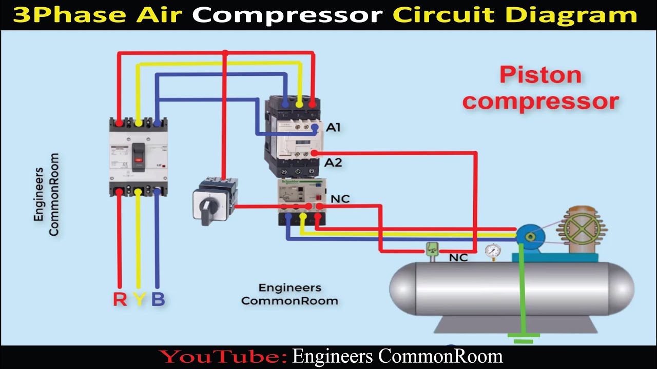
Air Compressor Motor Wiring Diagram Air Conditioning How To Modify A

Compressor Unit Flow Diagram. | Download Scientific Diagram

Compressor Control System • OEM Panels
How to compressor works

Flow: How Air and Oil Flow in Screw Air Compressor- Engihub

Solved Fig. 3 shows a schematic diagram of an air compressor | Chegg.com